
This installation and maintenance manual explains how to install and maintain electric actuators. Information on installation, disassembly, reassembly, operation, troubleshoot and parts is provided. Every actuators manufacturer should provide an installation and maintenance manual to its customer but in some cases, they are incomplete or don’t even make it to the end-user on the field. So here is a somehow generic installation, operation and maintenance manual that could be used for most electric actuators on the market.
Note: our installation/maintenance manuals, specific to Indelac actuators, can be found here.
STORAGE
If the actuators are scheduled for installation at a later date:
- Store off the floor
- Store in a climate controlled building
- Store in a clean and dry area
SUGGESTED MAXIMUM TORQUE VALUES FOR FASTENERS (In-Lb)
|
INSTALLATION
Most of the time, the actuator is shipped in the open position from the factory, it is important to make sure the valve and actuator are in the same position before mounting the actuator on the valve.
1. Manually open valve.
2. Remove valve mechanical stops.
CAUTION: DO NOT REMOVE ANY PARTS NECESSARY FOR THE PROPER OPERATION OF THE VALVE, I.E., PACKING GLAND, GLAND NUT, ETC.
3. Check again that the valve and actuator are in the same position.
4. Install mounting hardware on valve, do not tighten bolts securely at this time, mount actuator to valve, and once actuator screws have been started securely tighten all nuts and bolts.
NOTE: ACTUATOR CONDUIT ENTRY IS NORMALLY POSITIONED PERPENDICULAR TO PIPE LINE.
5. Remove actuator cover.
6. Wire actuator using proper wiring diagram. Indelac supplies the appropriate wiring diagram inside the cover of each actuator.
CAUTION: BE SURE POWER IS OFF AT THE MAIN POWER BOX.
7. Turn on power to actuator.
CAUTION: USE EXTREME CAUTION, AS THERE ARE LIVE CIRCUITS THAT COULD CAUSE ELECTRICAL SHOCK OR DEATH.
8. Operate the valve to the close position, check the alignment.
9. Operate the valve to the open position, check the alignment.
10. Replace cover and secure cover screws.
RECOMMENDED SPARE PARTS
You should always have some spare parts handy on-site to avoid long shutdown in case of an actuator malfunction. We recommand:
- Two Position Actuators: Set of cams and switches.
- Modulating Actuators: Set of cams, switches, feedback potentiometer and a positioner.
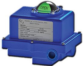
FOR FUTURE REFERENCE RECORD
- Actuator model number (usually located on the actuator enclosure)
- Actuator enclosure NEMA rating (NEMA 4, NEMA 4X, NEMA 7, NEMA 7…)
- Actuator output torque (In-Lbs.)
- Motor characteristics (voltage, hertz & phase)
- Date of installation
- Valve Data
-
Manufacturer
-
Style & fig. No.
-
Size
-
End connection
-
Material of construction (for the body, the stem & the ball)
-
Brake away torque (in Lbs-In @ PSI)
-
Media (temperature max/mini [°F] & pressure [PSI])
-
As this information is listed it is important to pay attention to all of the actuator specifications relative to the valve specifications and system requirements. If the actuator is not properly sized for the valve and application the life will be shortened or it may not work at all.
TROUBLESHOOTING
NOTES ON MAINTENANCE PROCEDURES: WARNING!!! In all cases, never operate an automated valve while under pressure or in a live process. Always disconnect supply air or voltage before any disassembly or maintenance is performed. Always be aware of the area classification for electrical service. Shut off and remove all electrical equipment from a hazardous area before performing any maintenance. If ever in doubt, choose safety first!
- Possible Cause
- Solution
Problem #1: Actuator will not operate
- Thermal Overload protection is active
- Allow actuator to cool. Decrease operating frequency
- Capacitor is loose or connected incorrectly
- Check wiring and diagram to correct capacitor connection
- Wires, switches or other leads may be disconnected or loose
- Inspect and re-connect
- Wires at terminal block loose or disconnected
- Inspect and re-connect
- Motor is damaged or otherwise inoperable
- Confirm voltage. Apply power without switches in circuit. Replace motor assembly
- Ambient temperature is too low causing inoperability
- Install heater and thermostat
- Optional components, control boards incorrectly installed or wiring is loose
- Check installation. Refer to wiring diagram. Replace or reinstall
Problem #2: Motor seems stalled. Power is ON but it will not operate
- Supply voltage (power) is applied to both sides of the motor simultaneously
- Check wiring. Make corrections
- System wiring has more than one actuator powered from same parallel source
- Apply isolating relays to control circuit
- Capacitor has failed
- Replace capacitor
- Valve requires too much operating torque
- Check valve torque. Look for obstructions
- Motor has failed
- Replace motor
- Failed control board components
- Inspect, re-wire or replace boards
Problem #3: Motor operates but output shaft does not turn
- Manual override (if supplied) is not properly engaged with gear train
- Manually engage override to the "automatic" position
- Damaged or stripped gears in drive train
- Replace gears or gearbox.
Problem #4: Actuator turns in one direction only
- Wires at terminal block loose or disconnected
- Check wiring. Make corrections
- Wires at the motor connection are loose or disconnected
- Check wiring. Make corrections
- Limit switch for the reverse direction is engaged with the cam
- Inspect and adjust the cam
- Failed control board component
- Inspect, re-wire or replace boards
- DC Motor – Polarity is not switching
- Install external switching/relay. See manufacturers wiring diagram
Problem #5: Actuator turns in the wrong direction
- Motor leads or limit switches are wired incorrectly
- Inspect and re-connect
- Actuator may be wired for unidirectional operation. Or may be a unidirectional model
- Refer to manufacturers wiring diagram. Re-wire
Problem #6: Actuator does not stop at the desired position
- Actuator rotation is limited by the action of a cam on the limit switch. Cam needs adjustment/setting
- Adjust/set cam
- Cam may be loose. Set screw is loose
- Adjust/set cam
- Limit switch is not working/contacting
- Replace limit switch
- Limit switches may be wired in reverse operation
- Inspect. Re-set
- Cam may be loose. Set screw is loose
- Adjust/set cam
- Limit switch is not working/contacting
- Replace limit switch
- Limit switches may be wired in reverse operation
- Inspect. Re-set
Problem #7: Moisture and/or corrosion is present inside enclosure
- Gasket seal is missing or installed incorrectly
- Replace gasket seal. Dry unit
- Water is entering through the conduit entry
- Inspect/Re-seal
- Cover was removed or left off during high humidity or rain
- Add a desiccant packet to the enclosure. Dry unit
- Cover not attached tightly or with the use of all cover bolts
- Dry unit. Tighten cover
- Humid environment
- Add Heater/Thermostat