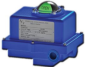
Here is a guide on how to fine-tune a Modulating Electric Actuator AC & DC Controls. The following instructions are a step by step manual for an easy and smooth field calibration.

Tools Required
- 3/16” wide flat head screwdriver
- DVM Digital voltmeter
Please Read These Instructions Completely Before Begining
1) Move motor / valve to 45⁰ - midway position between open and close.


2) Loosen set screw on the potentiometer shaft gear.
3) Turn power to the actuator off so that the motor does not move.

4) Remove the bottom J1 green connector from the controller board where the potentiometer is connected to.
5) Using a DVM, measure the resistance of the potentiometer between terminals 2 & 3.
6) Rotate the potentiometer shaft gear until the resistance reads approximately 500 ohms (+/-10).
7) Tighten down the potentiometer shaft gear set screw to lock in place.

8) Reconnect the green connector back into the controller board, J1.
9) Connect a 4-20mA signal generator to pins 4 & 5 at the top J2 green connector and set the input signal to 12.0mA to the actuator [pin 4 = (-) & pin 5 = (+)].
10) Turn the power back on to the actuator.

11) Make sure the Deadband pot on the controller board is at mid position.
12) Adjust the Zero Pot so that both LEDs are OFF with the valve at mid position and the signal at 12mA.
13) The motor/valve may move a little, but should not move much.
14) At the control signal, set the input signal to 4mA.
15) Adjust the ZERO pot on the controller board to the valve closed position. Make sure that the Green LED turns off and that the Red LED does not turn on.
16) Set the input signal to 20mA.
17) Adjust the SPAN pot on the controller board to the valve open position. Make sure that the Red LED turns off and that the Green LED does not turn on.
18) Repeat steps 13 thru 16 at least 4 more times to get the final position adjustment – each adjustment will affect the last one done. After 4 cycles of adjustment, the open and close will be set.
 19) If the OPEN and CLOSE CAMS need to be adjusted to allow further valve movement, this may be done as well. Loosen the set screw for the CAM that needs to be adjusted and rotate the CAM to allow more or less motion.
20) The CAM should be adjusted so that the switch opens AFTER the LED goes off. Open and Close the valve once more to verify the LED goes off BEFORE the switch opens.
21) Re-tighten the set screw & replace the actuator cover.
Step by Step Video


